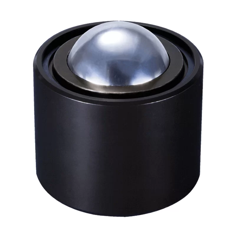
MI Series Medium-Duty Ball Transfers
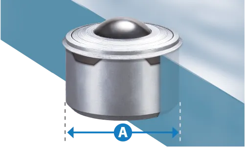
Switch measurements:
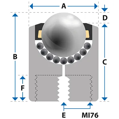
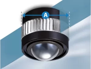
| Part | Load (lb)Load (kg) | Weight | BALL ⌀ ″Ball Ø (mm) | A | B | C | D | E | F | $ from |  | |
|---|---|---|---|---|---|---|---|---|---|---|---|---|
| MI12 | 55 25 | 0.110 0.050 | 1/2" 12 | 0.866 ❋22 ❋ | 0.945 24 | 0.807 20.5 | 0.138 3.5 | M8 x 1.25 M8 x 1.25 | 0.197 5 | $28.44 | PDF Step | |
| MI15 | 132 60 | 0.163 0.074 | 5/8" 15 | 0.945 24 | 1.102 28 | 0.906 23 | 0.197 5 | M8 x 1.25 M8 x 1.25 | 0.315 8 | $28.91 | PDF Step | |
| MI22 | 397 180 | 0.560 0.254 | 7/8" 22 | 1.417 36 | 1.594 40.5 | 1.417 36 | 0.177 4.5 | M8 x 1.25 M8 x 1.25 | 0.394 10 | $32.52 | PDF Step | |
| MI30 | 772 350 | 1.014 0.460 | 1 3/16" 30 | 1.772 45 | 1.843 46.8 | 1.528 38.8 | 0.256 6.5 | M8 x 1.25 M8 x 1.25 | 0.394 10 | $48.02 | PDF Step | |
| MI45 | 1323 600 | 2.601 1.180 | 1 3/4" 45 | 2.441 62 | 2.500 63.5 | 1.988 50.5 | 0.354 9 | M8 x 1.25 M8 x 1.25 | 0.394 10 | $126.50 | PDF Step | |
| MI76 | 2200 1000 | 13.360 6.060 | 3" 76.2 | 5 ●127 ● | 3.992 101.4 | 3.075 78.1 | 0.917 23.3 | 3.5" x 8 TPI NPSM 3.5" x 8 TPI NPSM | 1.467 37.3 | $216.33 | ||
| MI12A | 44 20 | 0.110 0.050 | 1/2" 12 | 0.866 ❋22 ❋ | 0.945 24 | 0.807 20.5 | 0.138 3.5 | M8 x 1.25 M8 x 1.25 | 0.197 5 | $35.15 | PDF Step | |
| MI15A | 110 50 | 0.163 0.074 | 5/8" 15 | 0.945 24 | 1.102 28 | 0.906 23 | 0.197 5 | M8 x 1.25 M8 x 1.25 | 0.315 8 | $36.70 | PDF Step | |
| MI22A | 397 180 | 0.564 0.256 | 7/8" 22 | 1.417 36 | 1.594 40.5 | 1.417 36 | 0.177 4.5 | M8 x 1.25 M8 x 1.25 | 0.394 10 | $42.15 | PDF Step | |
| MI30A | 772 350 | 0.992 0.450 | 1 3/16" 30 | 1.772 45 | 1.843 46.8 | 1.528 38.8 | 0.256 6.5 | M8 x 1.25 M8 x 1.25 | 0.394 10 | $58.13 | PDF Step | |
| MI45A | 1323 600 | 2.579 1.170 | 1 3/4" 45 | 2.441 62 | 2.500 63.5 | 1.988 50.5 | 0.354 9 | M8 x 1.25 M8 x 1.25 | 0.394 10 | $174.02 | PDF Step | |
| MI76A | 2200 1000 | 13.338 6.050 | 3" 76.2 | 5 ●127 ● | 3.992 101.4 | 3.075 78.1 | 0.917 23.3 | 3.5" x 8 TPI NPSM 3.5" x 8 TPI NPSM | 1.467 37.3 | $787.21 | ||
| MI12D | 11 5 | 0.095 0.043 | 1/2" 12 | 0.866 ❋22 ❋ | 0.945 24 | 0.807 20.5 | 0.138 3.5 | M8 x 1.25 M8 x 1.25 | 0.197 5 | $33.26 | PDF Step | |
| MI15D | 22 10 | 0.134 0.061 | 5/8" 15 | 0.945 24 | 1.102 28 | 0.906 23 | 0.197 5 | M8 x 1.25 M8 x 1.25 | 0.315 8 | $35.65 | PDF Step | |
| MI22D | 44 20 | 0.463 0.210 | 7/8" 22 | 1.417 36 | 1.594 40.5 | 1.417 36 | 0.177 4.5 | M8 x 1.25 M8 x 1.25 | 0.394 10 | $26.27 | PDF Step | |
| MI30D | 55 25 | 0.794 0.360 | 1 3/16" 30 | 1.772 45 | 1.843 46.8 | 1.528 38.8 | 0.256 6.5 | M8 x 1.25 M8 x 1.25 | 0.394 10 | $61.75 | PDF Step | |
| MI45D | 55 25 | 2.095 0.950 | 1 3/4" 45 | 2.441 62 | 2.500 63.5 | 1.988 50.5 | 0.354 9 | M8 x 1.25 M8 x 1.25 | 0.394 10 | $190.07 | PDF Step | |
| MI76D | 55 25 | 10.064 4.565 | 3" 76.2 | 5 ●127 ● | 3.992 101.4 | 3.075 78.1 | 0.917 23.3 | 3.5" x 8 TPI NPSM 3.5" x 8 TPI NPSM | 1.467 37.3 | $787.21 | ||
| MI22SS | Inquire Inquire | Inquire Inquire | 7/8" 22 | 1.417 36 | 1.594 40.5 | 1.417 36 | 0.177 4.5 | M8 x 1.25 M8 x 1.25 | 0.394 10 | - | ||
| MI30SS | Inquire Inquire | Inquire Inquire | 1 3/16" 30 | 1.772 45 | 1.843 46.8 | 1.528 38.8 | 0.256 6.5 | M8 x 1.25 M8 x 1.25 | 0.394 10 | - | ||
| MI45SS | Inquire Inquire | Inquire Inquire | 1 3/4" 45 | 2.441 62 | 2.500 63.5 | 1.988 50.5 | 0.354 9 | M8 x 1.25 M8 x 1.25 | 0.394 10 | - | ||
| MI76SS | Inquire Inquire | Inquire Inquire | 3" 76.2 | 5 ●127 ● | 3.992 101.4 | 3.075 78.1 | 0.917 23.3 | 3.5" x 8 TPI NPSM 3.5" x 8 TPI NPSM | 1.467 37.3 | - |
Also consider
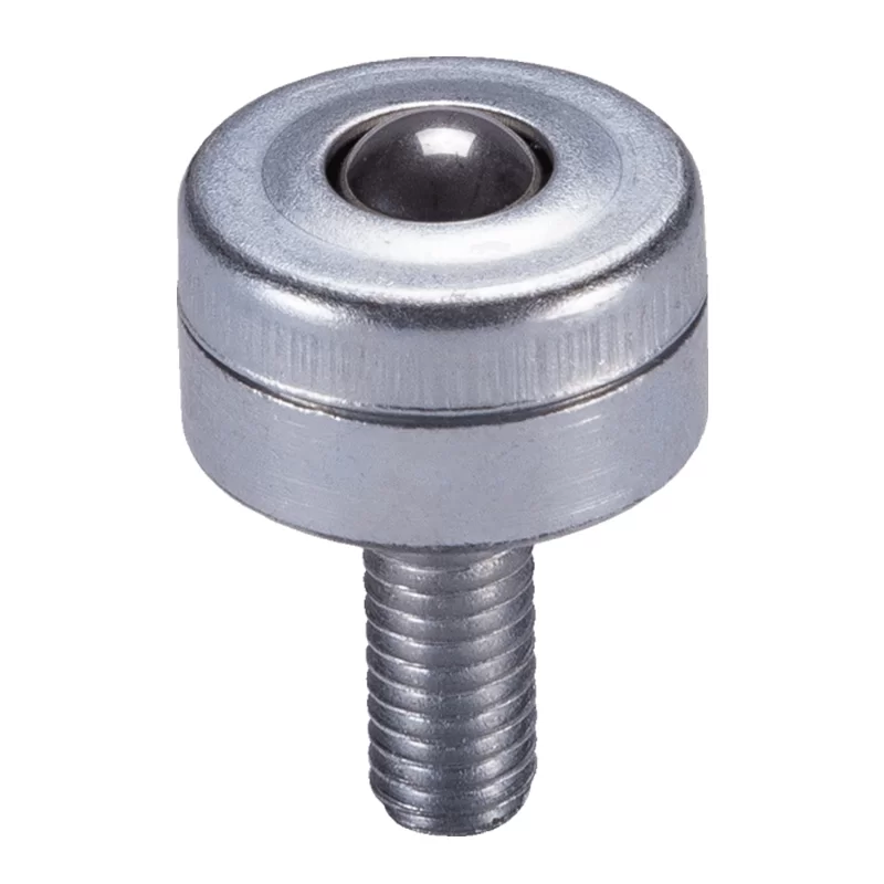
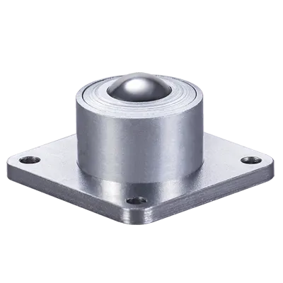
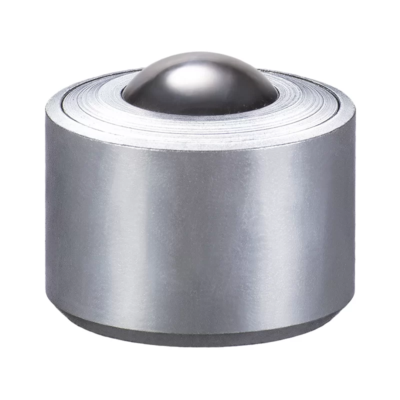
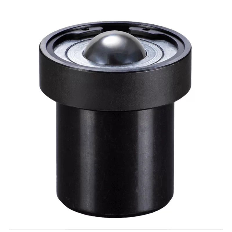
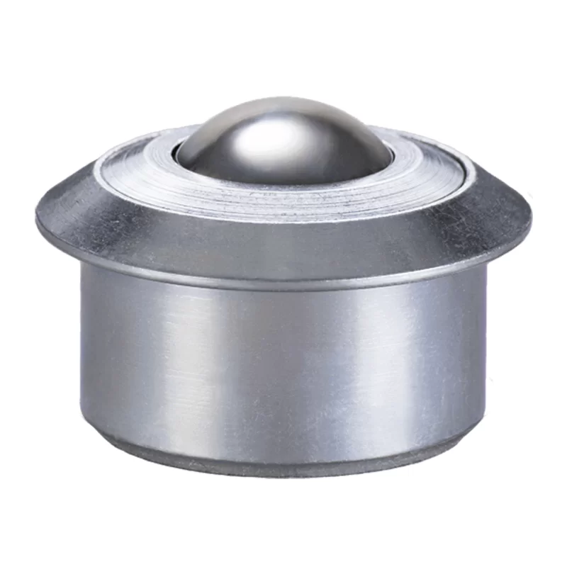
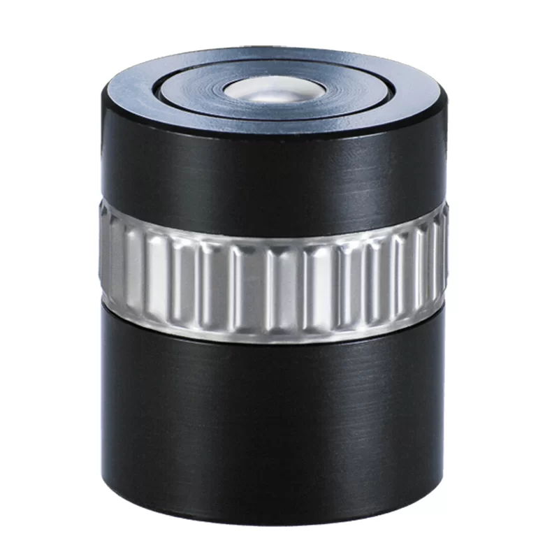
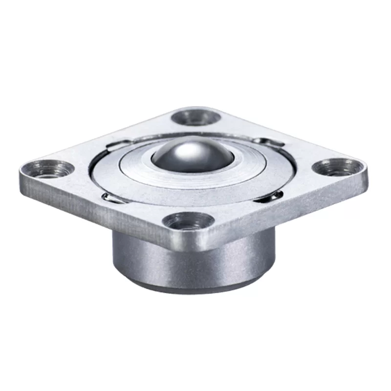
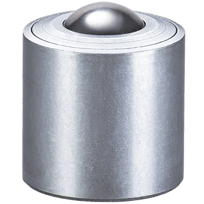
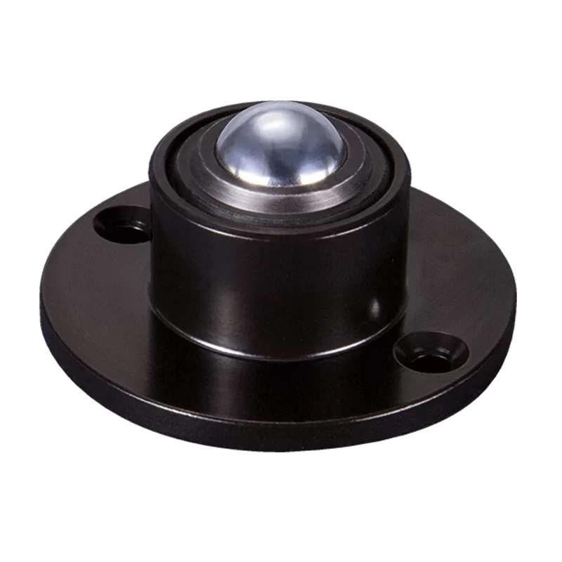
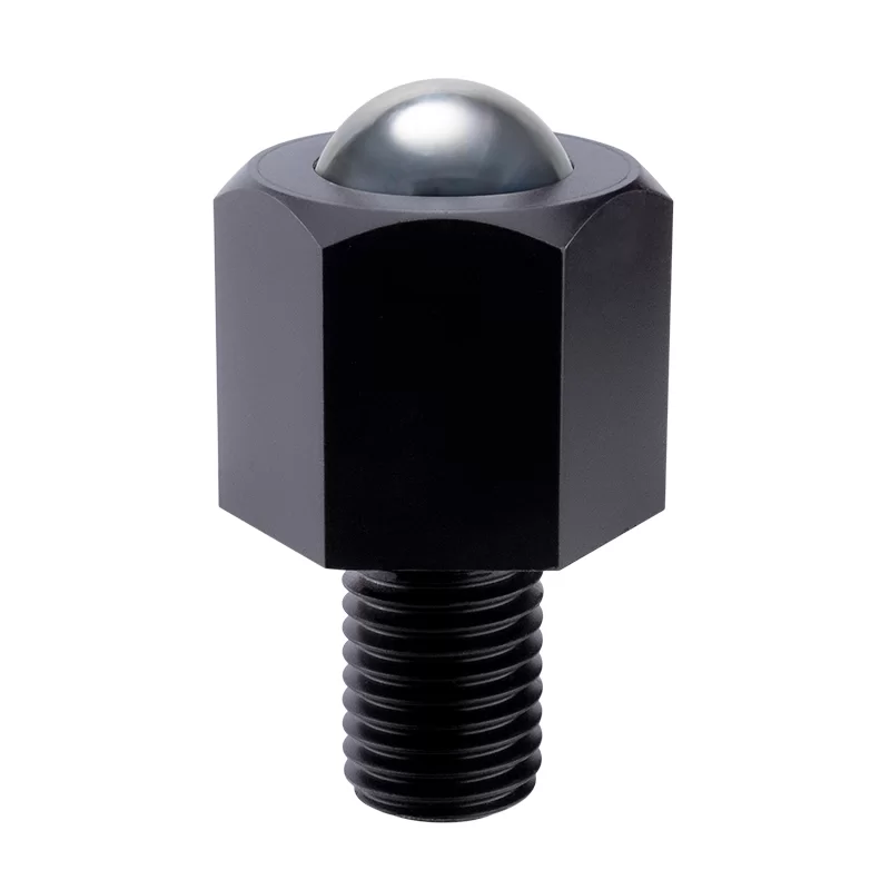
Our MI series medium duty range of ball transfer units are machined from solid steel & case hardened for wear resistance. Reinforced machined steel top cap protecting it against impact from any misalignment of conveyed items.
Lubricated for life & zinc plated for resistance to corrosion. Standard materials; Body & cap AISI 1015, Balls AISI 52100. Stainless steel upgrade ‘A’ & ‘SS’ feature AISI420 balls Shock Resistance & body. Main ball sizes ≥19mm incorporate a felt seal to restrict contamination.
This series features a single drain hole. M8 internal securing thread (female).
1 : 0,02
1.5m/sec
-30/+100ºC
Orientation Horizontal / Up
K & C Type Clips
- Fixing clips compensate for irregularities in bore and diameter.
- Ideal where only single-sided access of mounting surface is reachable.
| Medium Duty | Part | Bore Ø MIN - MAX | A | $ from | | |
|---|---|---|---|---|---|---|
| MI12 | K12 | 0.905 - 0.925 23.0 - 23.5 | 0.866 22 | $1.46 | ||
| MI15 | K15 | 0.984 - 1.004 25.0 - 25.5 | 0.945 24 | $1.62 | ||
| MI15 | C15 | 0.976 – 0.984 24.8 - 25.0 | 0.945 24 | $2.44 | ||
| MI22 | K22 | 1.457 - 1.476 37.0 - 37.5 | 1.417 36 | $1.81 | ||
| MI22 | C22 | 1.457 - 1.465 37.0 - 37.2 | 1.417 36 | $2.80 | ||
| MI30 | K30 | 1.811 - 1.831 46.0 - 46.5 | 1.772 45 | $2.51 | ||
| MI30 | C30 | 1.823 - 1.839 46.3 - 46.7 | 1.772 45 | $3.82 | ||
| MI45 | K45 | 2.480 - 2.500 63.0 - 63.5 | 2.441 62 | $3.52 |
- Fit clip to mounting bore.
- Push ball unit though clip.
- Peripheral tags expand & grip the ball unit.
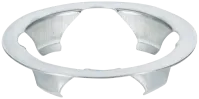
K-clip Spring Steel
C-clip Spring Steel

Other clips available.
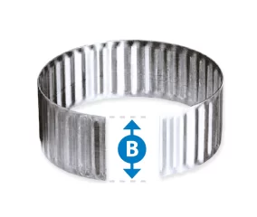
Tolerance Rings
- Compensate for irregularities in bore & diameter.
- Ideal where only single-sided access of mounting surface is reachable.
| Medium Duty | Part | A | Bore Ø MIN / MAX | B | $ from | | |
|---|---|---|---|---|---|---|---|
| MI12 | TR20 | 0.787 20 | 0.858 - 0.868 21.80 - 22.05 | 0.472 12 | $1.19 | ||
| MI15 | TR24 | 0.945 24 | 1.010 - 1.020 25.65 - 25.90 | 0.591 15 | $1.33 | ||
| MI22 | TR36 | 1.417 36 | 1.488 - 1.496 37.80 - 38.00 | 0.472 12 | $2.08 | ||
| MI30 | TR45 | 1.772 45 | 1.843 - 1.850 46.80 - 47.00 | 0.591 15 | $2.17 | ||
| TR60 | 2.362 60 | 2.445 - 2.453 62.10 - 62.30 | 0.787 20 | $2.69 |

Can’t find what you’re looking for?
Try searching for key-words, part numbers, load, fixing types.