MG Series Ball Transfer Units for Medium-Duty Applications
Feature to display below:
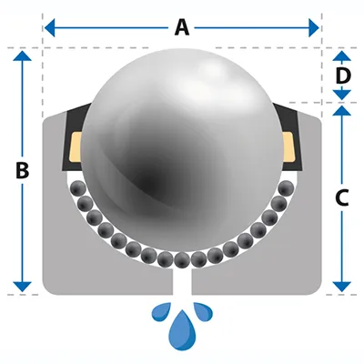
| Part | Load (lb)Load (kg) | £ from | ||||||||
|---|---|---|---|---|---|---|---|---|---|---|
| MG8 | 29 13 | 0.037 0.017 | 5/16" 8 | 0.709 18 | 0.472 12 | 0.394 10 | 0.079 2 | £2.88 | PDF Step | |
| MG10 | 55 25 | 0.062 0.028 | 1/2" 10 | 0.787 20 | 0.650 16.5 | 0.531 13.5 | 0.118 3 | £6.85 | PDF Step | |
| MG12 | 55 25 | 0.077 0.035 | 1/2" 12 | 0.866 ❋22 ❋ | 0.689 17.5 | 0.551 14 | 0.118 3 | £5.97 | PDF Step | |
| MG15 | 132 60 | 0.108 0.049 | 5/8" 15 | 0.945 24 | 0.787 20 | 0.591 15 | 0.197 5 | £8.11 | PDF Step | |
| MG22 | 397 180 | 0.390 0.177 | 7/8" 22 | 1.417 36 | 1.201 30.5 | 1.023 26 | 0.177 4.5 | £8.20 | PDF Step | |
| MG30 | 772 350 | 0.739 0.335 | 1 3/16" 30 | 1.772 45 | 1.449 36.8 | 1.193 30.3 | 0.256 6.5 | £10.62 | PDF Step | |
| MG45 | 1323 600 | 2.072 0.940 | 1 3/4" 45 | 2.441 62 | 2.106 53.5 | 1.772 45 | 0.354 9 | £29.86 | PDF Step | |
| MG60 | 3307 1500 | 8.047 3.650 | 2 3/8" 60 | 3.937 100 | 3.051 77.5 | 2.402 61 | 0.650 16.5 | £122.01 | PDF Step | |
| MG76 | 5512 2500 | 18.960 8.600 | 3" 76 | 5.118 130 | 4.055 103 | 3.150 80 | 0.906 23 | £268.76 | PDF Step | |
| MG90 | 7716 3500 | 24.934 11.310 | 3 1/2" 90 | 5.709 145 | 4.528 115 | 3.543 90 | 0.984 25 | £314.63 | PDF Step | |
| MG8A | 22 10 | 0.040 0.018 | 5/16" 8 | 0.709 18 | 0.472 12 | 0.394 10 | 0.079 2 | £5.36 | PDF Step | |
| MG10A | 44 20 | 0.062 0.028 | 1/2" 10 | 0.787 20 | 0.650 16.5 | 0.531 13.5 | 0.118 3 | £8.19 | PDF Step | |
| MG12A | 44 20 | 0.075 0.034 | 1/2" 12 | 0.866 ❋22 ❋ | 0.689 17.5 | 0.551 14 | 0.118 3 | £7.33 | PDF Step | |
| MG15A | 110 50 | 0.106 0.048 | 5/8" 15 | 0.945 24 | 0.787 20 | 0.591 15 | 0.197 5 | £8.41 | PDF Step | |
| MG22A | 397 180 | 0.392 0.178 | 7/8" 22 | 1.417 36 | 1.201 30.5 | 1.023 26 | 0.177 4.5 | £9.62 | PDF Step | |
| MG30A | 772 350 | 0.745 0.338 | 1 3/16" 30 | 1.772 45 | 1.449 36.8 | 1.193 30.3 | 0.256 6.5 | £12.02 | PDF Step | |
| MG45A | 1323 600 | 2.139 0.970 | 1 3/4" 45 | 2.441 62 | 2.106 53.5 | 1.772 45 | 0.354 9 | £35.51 | PDF Step | |
| MG60A | 2425 1100 | 7.916 3.590 | 2 3/8" 60 | 3.937 100 | 3.051 77.5 | 2.402 61 | 0.650 16.5 | £132.62 | PDF Step | |
| MG76A | 3748 1700 | 18.960 8.600 | 3" 76 | 5.118 130 | 4.055 103 | 3.150 80 | 0.906 23 | £315.55 | PDF Step | |
| MG90A | 5291 2400 | 24.934 11.310 | 3 1/2" 90 | 5.709 145 | 4.528 115 | 3.543 90 | 0.984 25 | £368.42 | PDF Step | |
| MG8D | 11 5 | 0.036 0.016 | 5/16" 8 | 0.709 18 | 0.472 12 | 0.394 10 | 0.079 2 | £4.71 | PDF Step | |
| MG10D | 11 5 | 0.049 0.022 | 1/2" 10 | 0.787 20 | 0.650 16.5 | 0.531 13.5 | 0.118 3 | £9.42 | PDF Step | |
| MG12D | 11 5 | 0.060 0.027 | 1/2" 12 | 0.866 ❋22 ❋ | 0.689 17.5 | 0.551 14 | 0.118 3 | £7.34 | PDF Step | |
| MG15D | 22 10 | 0.077 0.035 | 5/8" 15 | 0.945 24 | 0.787 20 | 0.591 15 | 0.197 5 | £8.53 | PDF Step | |
| MG22D | 44 20 | 0.309 0.140 | 7/8" 22 | 1.417 36 | 1.201 30.5 | 1.023 26 | 0.177 4.5 | £10.70 | PDF Step | |
| MG30D | 55 25 | 0.551 0.250 | 1 3/16" 30 | 1.772 45 | 1.449 36.8 | 1.193 30.3 | 0.256 6.5 | £18.28 | PDF Step | |
| MG45D | 55 25 | 1.609 0.730 | 1 3/4" 45 | 2.441 62 | 2.106 53.5 | 1.772 45 | 0.354 9 | £52.69 | PDF Step | |
| MG60D |
| 2 3/8" 60 | 3.937 100 | 3.051 77.5 | 2.402 61 | 0.650 16.5 | - | |||
| MG76D |
| 3" 76 | 5.118 130 | 4.055 103 | 3.150 80 | 0.906 23 | - | |||
| MG90D |
| 3 1/2" 90 | 5.709 145 | 4.528 115 | 3.543 90 | 0.984 25 | - | |||
| MG8SS | Inquire Inquire | Inquire Inquire | 5/16" 8 | 0.709 18 | 0.472 12 | 0.394 10 | 0.079 2 | - | ||
| MG10SS | Inquire Inquire | Inquire Inquire | 1/2" 10 | 0.787 20 | 0.650 16.5 | 0.531 13.5 | 0.118 3 | - | ||
| MG12SS | Inquire Inquire | Inquire Inquire | 0.47 12 | 0.866 ❋22 ❋ | 0.689 17.5 | 0.551 14 | 0.118 3 | - | ||
| MG15SS | Inquire Inquire | Inquire Inquire | 5/8" 15 | 0.945 24 | 0.787 20 | 0.591 15 | 0.197 5 | - | ||
| MG22SS | Inquire Inquire | Inquire Inquire | 7/8" 22 | 1.417 36 | 1.201 30.5 | 1.024 26 | 0.177 4.5 | - | ||
| MG30SS | Inquire Inquire | Inquire Inquire | 1 3/16" 30 | 1.772 45 | 1.449 36.8 | 1.193 30.3 | 0.256 6.5 | - | ||
| MG45SS | Inquire Inquire | Inquire Inquire | 1 3/4" 45 | 2.441 62 | 2.106 53.5 | 1.772 45 | 0.354 9 | - | ||
| MG60SS | Inquire Inquire | Inquire Inquire | 2 3/8" 60 | 3.937 100 | 3.051 77.5 | 2.402 61 | 0.650 16.5 | - | ||
| MG76SS | Inquire Inquire | Inquire Inquire | 3" 76 | 5.118 130 | 4.055 103 | 3.150 80 | 0.906 23 | - | ||
| MG90SS | Inquire Inquire | Inquire Inquire | 3 1/2" 90 | 5.709 145 | 4.528 115 | 3.543 90 | 0.984 25 | - | ||
| MG8 | 29 13 | |||||||||
| MG10 | 55 25 | |||||||||
| MG12 | 55 25 | |||||||||
| MG15 | 132 60 | |||||||||
| MG22 | 397 180 | |||||||||
| MG30 | 772 350 | |||||||||
| MG45 | 1323 600 | |||||||||
| MG60 | 3307 1500 | |||||||||
| MG76 | 5512 2500 | |||||||||
| MG90 | 7716 3500 | |||||||||
| MG8A | 22 10 | |||||||||
| MG10A | 44 20 | |||||||||
| MG12A | 44 20 | |||||||||
| MG15A | 110 50 | |||||||||
| MG22A | 397 180 | |||||||||
| MG30A | 772 350 | |||||||||
| MG45A | 1323 600 | |||||||||
| MG60A | 2425 1100 | |||||||||
| MG76A | 3748 1700 | |||||||||
| MG90A | 5291 2400 | |||||||||
| MG8D | 11 5 | |||||||||
| MG10D | 11 5 | |||||||||
| MG12D | 11 5 | |||||||||
| MG15D | 22 10 | |||||||||
| MG22D | 44 20 | |||||||||
| MG30D | 55 25 | |||||||||
| MG45D | 55 25 | |||||||||
| MG60D |
| |||||||||
| MG76D |
| |||||||||
| MG90D |
| |||||||||
| MG8SS | Inquire Inquire | |||||||||
| MG10SS | Inquire Inquire | |||||||||
| MG12SS | Inquire Inquire | |||||||||
| MG15SS | Inquire Inquire | |||||||||
| MG22SS | Inquire Inquire | |||||||||
| MG30SS | Inquire Inquire | |||||||||
| MG45SS | Inquire Inquire | |||||||||
| MG60SS | Inquire Inquire | |||||||||
| MG76SS | Inquire Inquire | |||||||||
| MG90SS | Inquire Inquire | |||||||||

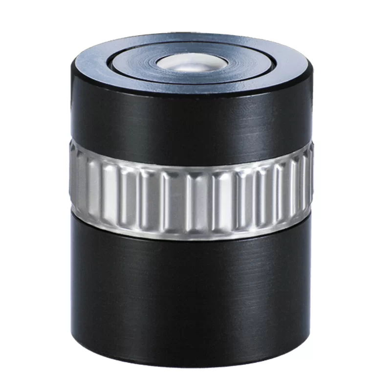
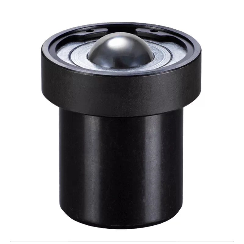
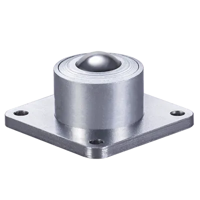
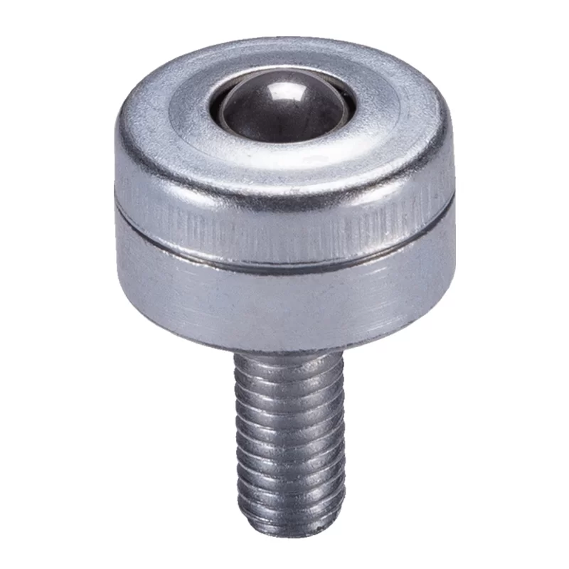
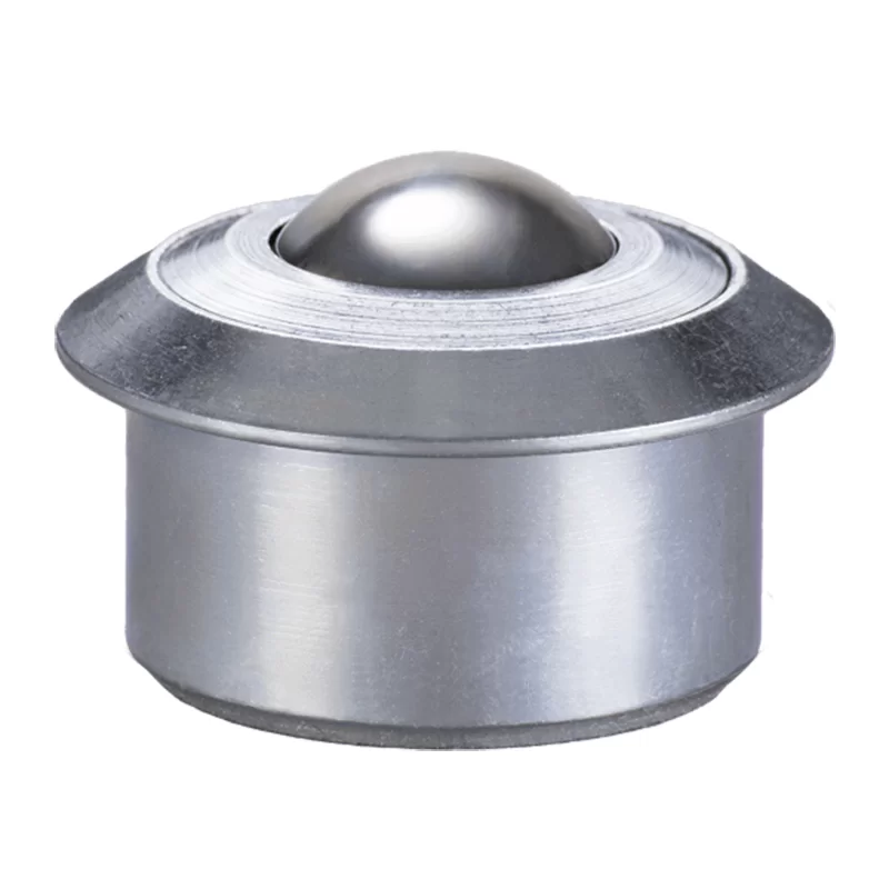
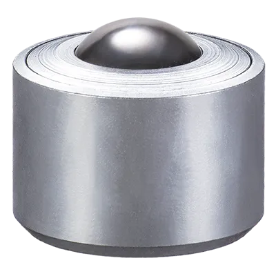
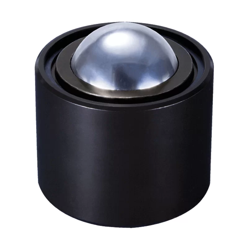
The MG series plain fitting medium duty ball transfer units are machined from solid steel & case hardened for wear resistance. Reinforced machined steel top cap to protect against impact from any misalignment of the conveyed item.
Lubricated for life & zinc plated for resistance to corrosion. Standard materials; Body & cap AISI 1015, Balls AISI 52100. Stainless steel upgrade ‘A’ & ‘SS’ feature AISI420 balls Shock Resistance & body. Main ball sizes ≥19mm incorporate a felt seal to restrict contamination.
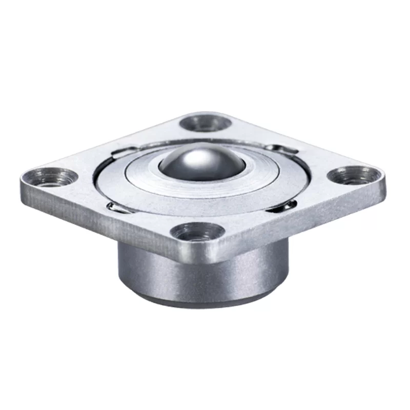
This series features a single drain hole. Base plate fixing.
1 : 0,02
1.5m/sec
-30/+100ºC
Orientation Horizontal / Up
K & C Type Clips
- Fixing clips compensate for irregularities in bore and diameter.
- Ideal where only single-sided access of mounting surface is reachable.
Feature to display below:
| Part | Medium Duty | £ from | ||||
|---|---|---|---|---|---|---|
| MG15 | K15 | 0.984 - 1.004 25.0 - 25.5 | 0.945 24 | £0.67 | ||
| MG15 | C15 | 0.976 – 0.984 24.8 - 25.0 | 0.945 24 | £0.91 | ||
| MG22 | K22 | 1.457 - 1.476 37.0 - 37.5 | 1.417 36 | £0.78 | ||
| MG30 | K30 | 1.811 - 1.831 46.0 - 46.5 | 1.772 45 | £1.09 | ||
| MG30 | C30 | 1.823 - 1.839 46.3 - 46.7 | 1.772 45 | £1.42 | ||
| MG45 | K45 | 2.480 - 2.500 63.0 - 63.5 | 2.441 62 | £1.53 | ||
| K15 | MG15 | |||||
| C15 | MG15 | |||||
| K22 | MG22 | |||||
| K30 | MG30 | |||||
| C30 | MG30 | |||||
| K45 | MG45 |
- Fit clip to mounting bore.
- Push ball unit though clip.
- Peripheral tags expand & grip the ball unit.
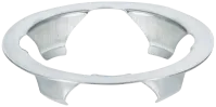
K-clip Spring Steel
C-clip Spring Steel

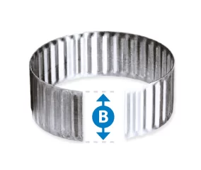
Tolerance Rings
- Compensate for irregularities in bore & diameter.
- Ideal where only single-sided access of mounting surface is reachable.
Feature to display below:
| Part | Medium Duty | £ from | |||||
|---|---|---|---|---|---|---|---|
| MG12 | TR20 | 0.787 20 | 0.858 - 0.868 21.80 - 22.05 | 0.472 12 | £0.54 | ||
| MG12 | TR22 | 0.866 22 | 0.937 - 0.947 23.80 - 24.05 | 0.472 12 | £0.58 | ||
| MG15 | TR24 | 0.945 24 | 1.010 - 1.020 25.65 - 25.90 | 0.591 15 | £0.60 | ||
| MG22 | TR36 | 1.417 36 | 1.488 - 1.496 37.80 - 38.00 | 0.472 12 | £1.16 | ||
| MG30 | TR45 | 1.772 45 | 1.843 - 1.850 46.80 - 47.00 | 0.591 15 | £1.17 | ||
| TR60 | 2.362 60 | 2.445 - 2.453 62.10 - 62.30 | 0.787 20 | £1.21 | |||
| MG60 | TR100 | 3.937 100 | 4.085 - 4.096 103.75 - 104.05 | 0.866 20 | £1.62 | ||
| TR20 | MG12 | ||||||
| TR22 | MG12 | ||||||
| TR24 | MG15 | ||||||
| TR36 | MG22 | ||||||
| TR45 | MG30 | ||||||
| TR60 | |||||||
| TR100 | MG60 |


Can’t find what you’re looking for?
Try searching for key-words, part numbers, load, fixing types.